Antiresonant versus resonant
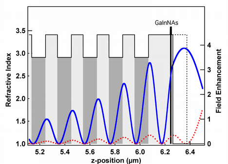

Example in Fig. 3 is given for a GaInNAs quantum well SESAM Download Ref. [194] (PDF, 155 KB) for which the top part of the multi-layer structure is shown with the refractive index profile (a). The dashed line indicates the increased thickness of the last layer which changes the SESAM design from a resonant to an antiresonant design. In blue and red we show the intensity distribution within the top part of the device for the resonant (blue) and the antiresonant (red) design which clearly shows about a 10 times increased intensity inside the quantum well absorber in the resonant design. (b) Measured linear reflectivity for the two SESAM designs where for the resonant design (blue) a clear reflectivity dip appears at resonance because of the increased loss of the quantum well absorber with higher field enhancement.
Trade-offs between antiresonant and resonant SESAM design is discussed in more details in Download Ref. [228] (PDF, 593 KB)